


This project was part of the laboratory curriculum of the Rose-Hulman cource titled "Communication Systems" (ECE310). This infrared digital communication system, which consists of a transmitter and a receiver circuit, was built by Elena Chong Loo and Lingtongyue Jin through five weeks of laboratory work. Two breadboards and electronics components, such as resistors, capacitors, op amps, etc, were purchased from the school electronics parts room and used as part of the circuit. The main purpose of this lab project was to provide the students with a better understanding of how the subsystems of the digital communication system--such as the comparator, sampler, modulator, and filters--work in tandem to enable digital communications.
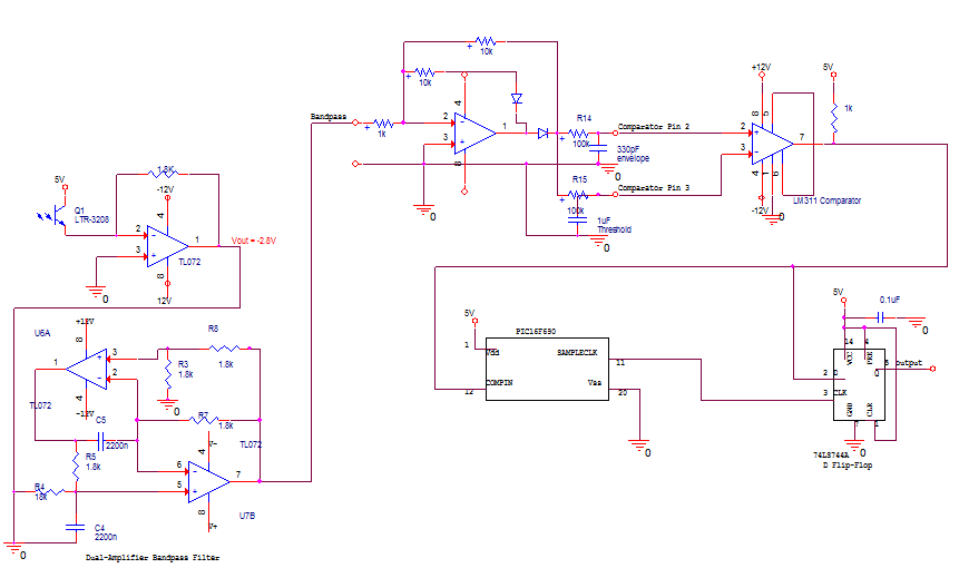
During every laboratory session, we designed, built, andverified the functionality of each stage using the equipment from the Elecrical Engineering lab. Datasheets were used to check the pin-out of each chip used in the circuit. As the project progressed, a schematic diagram was made for each component using PSpice OrCAD Capture. Two PIC16F690 chips, programmed using the MPLAB IDE software, were used in this lab.
Trasmitter breadboard
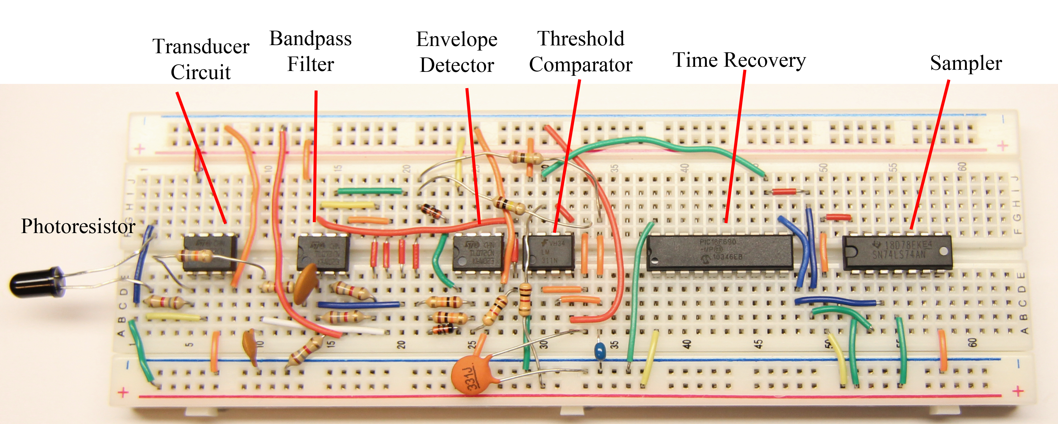
Receiver breadboard